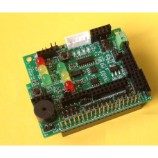
The EDU Learning Board serves as a multifaceted educational tool, allowing users to explore and control various modules and sensors, ranging from simulating traffic light systems with LEDs to reading an ultrasonic sensor, making it an invaluable resource for understanding and experimenting with a wide array of electronic components and systems.
Features
This EDU Learning Board can be used to learn how to: simulate traffic light systems using LEDs, control a stepper motor, control a PIR motion sensor, control an IR Receiver sensor, control an RFID reader, control an NRF24L01 module, control an ESP8266 WiFi module, control a Bluetooth 2.0/4.0 BLE module, control a buzzer, control a mini fan, control a 16x2/20x4 character LCD module, control a 84x48 Pixels Monochrome LCD module, read/write a 24c32 HAT EEPROM, read/write a Real Time Clock (RTC), read a 1-Wire DS18B20 temperature sensor, read a DHT22 Temperature & Humidity sensor, read an HY-SRF05 Ultrasonic Distance sensor.
- Two sets of traffic light simulation systems with two switches each imitating pedestrian crossing buttons:
- First set of traffic lights: Red (GPIO 19), Yellow (GPIO 13), Green (GPIO12), Switch 1 (GPIO 20)
- Second set of traffic lights: Red (GPIO 16), Yellow (GPIO 21), Green (GPIO 26), Switch 2 (GPIO 6)
- A 5V 28BYJ-48 stepper motor socket (GPIO 17, 18, 27, 22)
- Using a jumper switch, the 5V can be sourced from the Pi board or an external power source
- A PIR motion sensor socket and an IR receiver sensor socket (GPIO 23)
- Both sensor sockets use the same GPIO, so you can only select and use one of the sensor sockets at any given time
- An RFID reader socket (SPI signal) and NRF24L01 socket (SPI signal)
- Both sockets use the same SPI signal, so you can only select and use one of the sockets at any given time
- An ESP8266 WiFi module socket and a Bluetooth 2.0/4.0 BLE module socket
- Both sockets use the same Pi serial port, so you can only select and use one of the sockets at any given time
- A 3.3V buzzer (GPIO 24)
- A 5V mini fan (GPIO 5)
- A 16x2/20x4 character LCD socket
- GPIO Pin 1 to Pin 16: VSS, VDD, V0, RS, RW, E, D0, D1, D2, D3, D4, D5, D6, D7, A, K
- VSS - GND, VDD - 5V, V0 - 10K trimpot, RS - GPIO 25, RW - GND, E - GPIO 24, A - 5V, K - GPIO 18
- 4-bit mode: D4 - GPIO 23, D5 -> 11 - GPIO 17, D6 - GPIO 27, D7 - GPIO 22
- J40 Pins 1-2: LCD backlight will always be on; J40 Pins 2-3: LCD backlight controlled by GPIO 18
- An 84x48 Pixels Monochrome LCD socket
- Din = GPIO 23, SCLK = GPIO 24, DC = GPIO 22, RST = GPIO 17, CS = GPIO 27
- Backlight control = GPIO 18
- A 24c32 HAT EEPROM
- A Real Time Clock (RTC) clock with CR1220 3V Backup Battery
- A 1-Wire DS18B20 temperature sensor socket (GPIO 4)
- A DHT22 Temperature & Humidity sensor socket (GPIO 27)
- An HY-SRF05 Ultrasonic Distance sensor socket (GPIO 27 and 22)
- Two extra i2c device input ports: one for 3.3V, one for 5V
- 3.3V power regulator for the 3.3V devices: RFID / NRF24L01 / ESP8266 / i2c devices
The new functions we added in the Edu Learning Board V2:
- 2 x Red, Yellow, and Green LED display stand sets
- 2 x Servomotor sockets
- 1x HAT EEPROM 24c32
- 1x DHT22 Temperature & Humidity sensor socket
- 1x HY-SRF05 Ultrasonic Distance sensor socket
- 1x 16x2/20x4 character LCD socket
- 1x 84x48 Pixels Monochrome LCD socket
Datasheet
- ESP8266 WiFi module socket: Spec; AT command - Datasheet and AT Example
- Bluetooth 2.0 BLE module socket: AT command - Datasheet
- Bluetooth 4.0 BLE module socket: AT command - Datasheet
Demo program
- Edu-Pack-V2 Demo software pack for Edu Learning Board-V2 E01 functions
Package Content
1x Edu Learning Board-V2 E01
1x User Manual
Raspberry Pi - Edu Learning Board-V2 E01
- Brand: Pridopia
- Product Code: edu-v2-e01
- Availability: 10 Weight: 70 g
-
£28.99


