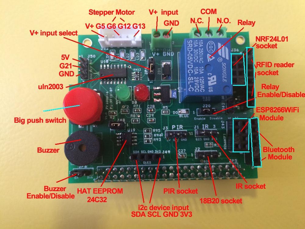
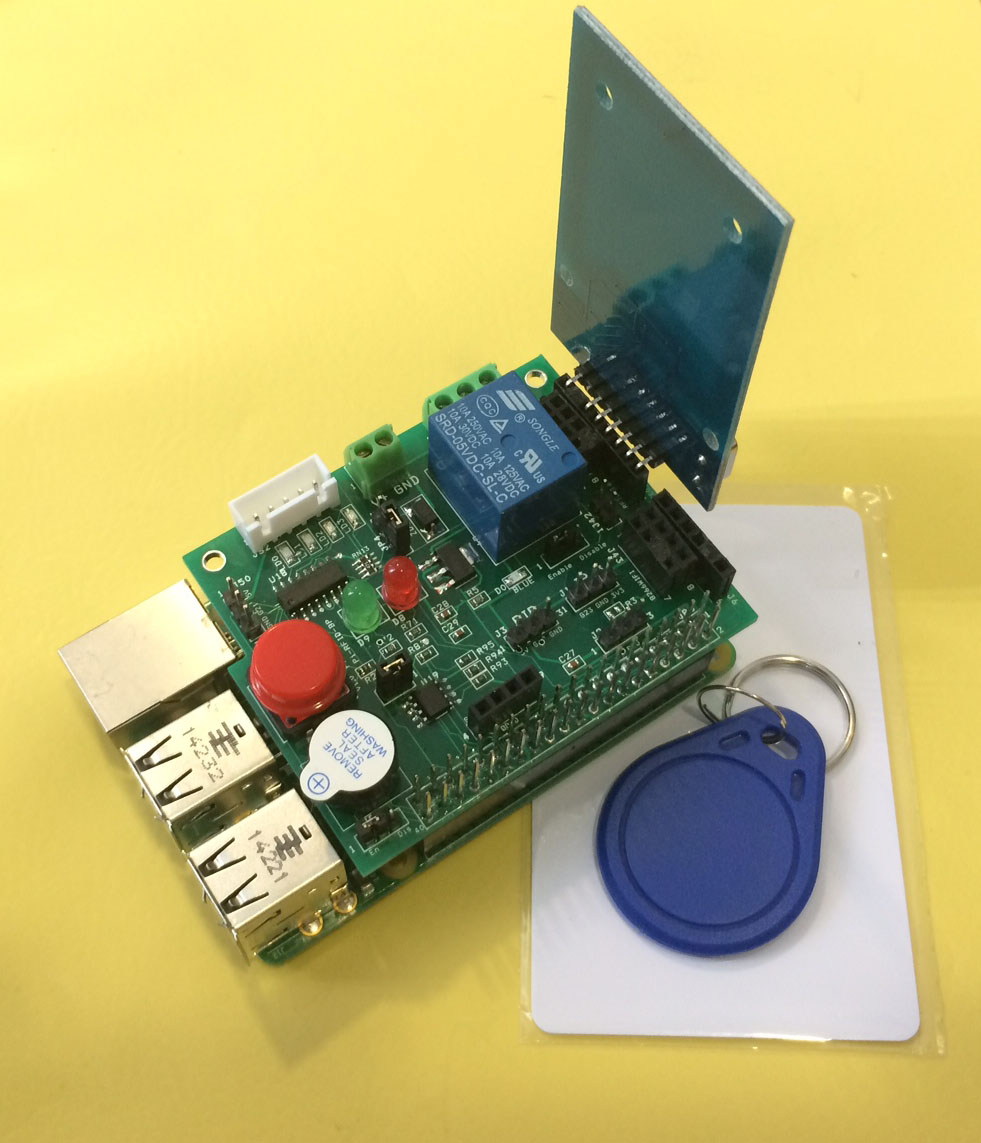
The RFID Reader
Board
1.
provide 1 buzzer (GPIO18)
2. provide 1 Big Push
Switch (GPIO27)
3.
Green LED
(GPIO19)
Red LED
(GPIO24)
4. provide RFID
socket ( SPI signal) / NRF24L01 socket (SPI signal)
you
can choose use RFID or NRF24L01 ( both use SPI
signal)
5. Provide 1 extra
i2c device input port, for 3.3V
device
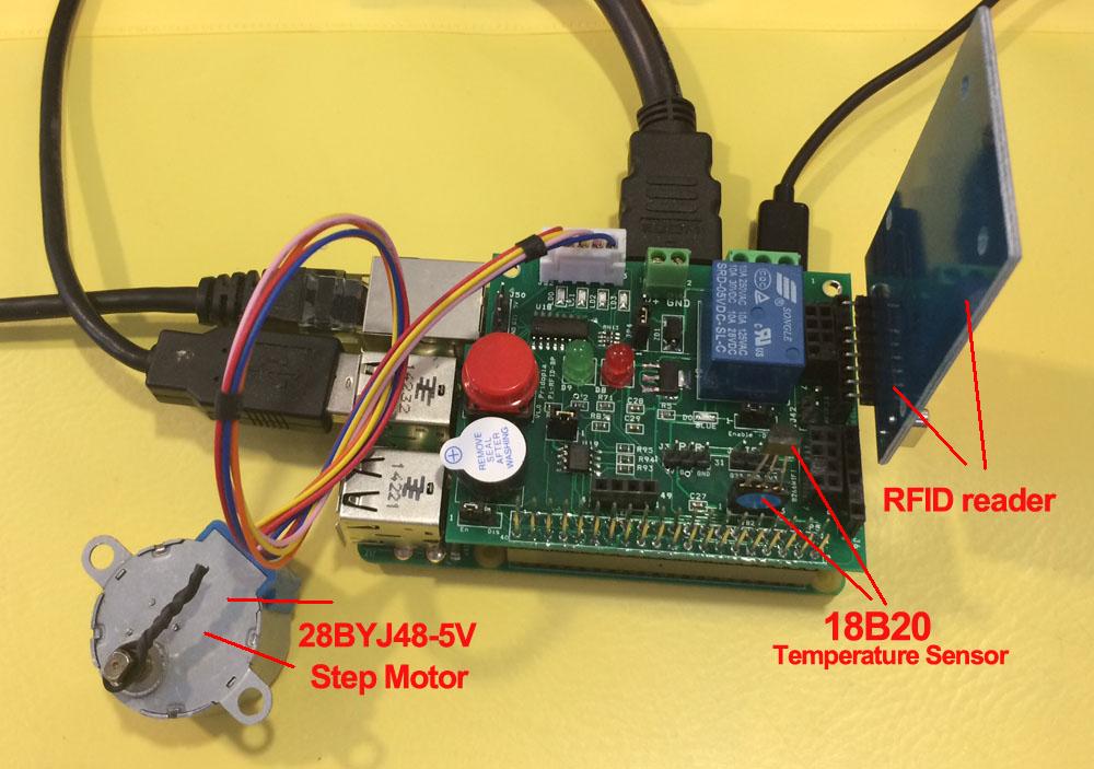
6. provide DS18B20
temperature sensor socket (GPIO4)
7. provide IR
Receiver sensor socket (GPIO23)
8. provide IR PIR
motion sensor socket (GPIO22)
9.
provide one Relay (GPIO17)
10.
1 step Motor (28byj48-5V) socket (GPIO
5,6,12,13)
11.
HAT EEPROM 24c32
12.
TXD, RXD Bluetooth module socket
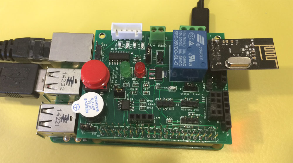
13.
ESP8266 WifI module socket
Click "RFID Panel " software will auto run with
terminal window
provide
GUI interface control software, easy to control
Relay, 18B20, stepper Motor
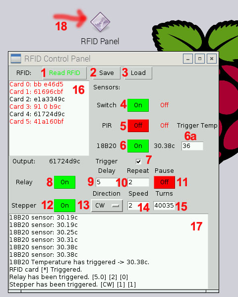
1. "Read RFID" read card information to Program
2. "Save" save card information to file
3. "Load" load card information from file
4. "on" turn on/off switch to trigger
5. "off" turn on/off PIR sensor to trigger
6. "on" turn on/off 18B20 sensor to trigger
6a. 18b20 temperature trigger ( Above will trigger the relay / stepper )
7. "Trigger" enable trigger for Relay & Stepper
Motor
8. Relay "On"/"Off" 9. Relay
delay time ? sec
10. Relay Repeat Count 11. Relay
Pause after repeating on/off
12. Stepper Motor "Off"/"On"
13. Stepper Motor Clock wise/counter clockwise
14. Stepper Motor speed ms/step
15. "Turns" how many steps you want stepper
motor turn
16. card information screen
17. System message screen
18. RFID control panel software icon
RFID Reader demo
18B20 Temperature sensor & Step Motor & RFID reader demo
NRF24L01 demo
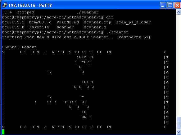
NRF24L01 WiFi Scanner demo
RFID reader plug-in RFID socket
MF RC522 is applied to
the highly integrated read and write
13.56MHz contactless
communication card chip
Low-voltage, low-cost,
small size of the non-contact card chip to read and
write
Smart meters and
portable handheld devices developed better choice
The MF RC522 use of
advanced modulation and demodulation concept
completely integrated in all types of 13.56MHz
passive contactless communication methods and
protocols
14443A compatible
transponder signals
The digital part of to
handle the ISO14443A frames and error detection.
support rapid CRYPTO1
encryption algorithm, terminology validation MIFARE
products
MFRC522 support MIFARE
series of high-speed non-contact communication,
two-way data transmission rate up to 424kbit/s
Specification:
Operating Current
:13-26mA/DC 3.3V
Idle Current
:10-13mA/DC 3.3V
Sleep Current: <80uA
Peak Current: <30mA
Operating Frequency:
13.56MHz
Supported card types:
mifare1 S50、mifare1 S70、mifare UltraLight、mifare
Pro、mifare Desfire
Environmental Operating
Temperature: -20-80 degrees Celsius
Environmental Storage
Temperature: -40-85 degrees Celsius
Relative humidity:
relative humidity 5% -95%
Data transfer rate:
maximum 10Mbit/s
Size: RFID-RC522
Module:3.9 x 6 cm The Standard S50 Blank Card :8.5 x
5.4 cm
Diameter of S50
special-shaped card: 3.1(max)
software support
Install tools for RFID kit in Raspberry Pi , in
our Pi_Scratch_v268 folder” Installer”
sudo python RFID-Installer.py
-- if you already install previous Pi_Scratch ver
already.
first time user, use
sudo python Install.py
RFID reader & Relay control
Support our Pi_Scratch software
Detail
Scratch control demo
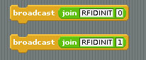
1)Command "RFID"+"INIT"+"0" for ce0
or "RFID"+"INIT"+"1" for ce1
will initial SPI signal to active RFID Reader
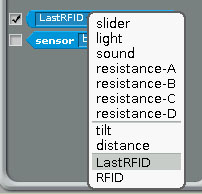
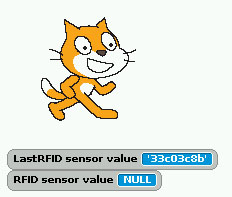
2) you will see "LastRFID" & "RFID" in Sensors
Scratch demo read RFID and GPIO output
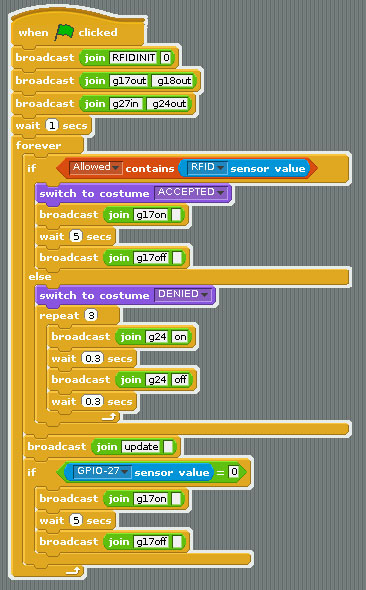
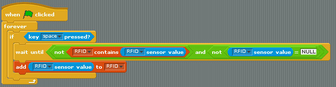
scratch demo code ( read
card and compare with database)
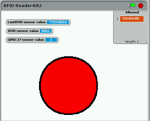
ADD RFID Card into data base
Press “space” key then scan your RFID card
Demo program
User
Manual
scratch demo file
RFID-Reader-kit2.sb RFIDdemo
RFID Relay Program
GUI interface
RFIDRelayDemo
|
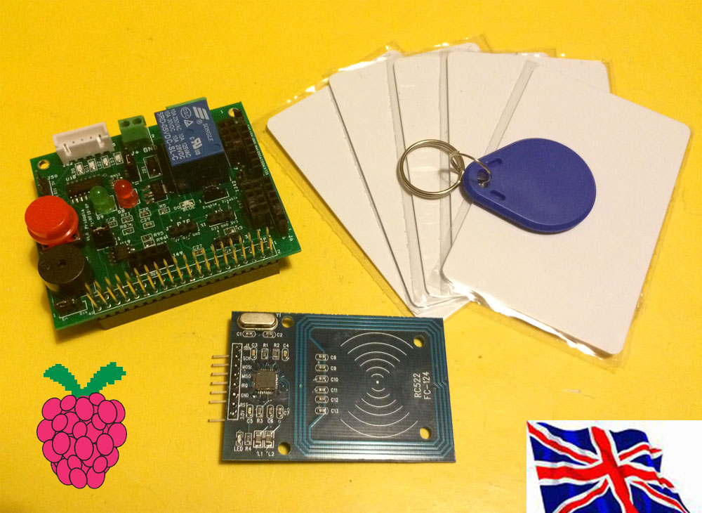
Package Content
1x Rs-Pi
RFID Reader
1x
Key Chains
5x
S50 Fudan Card
1x
RFID Kit03 Board
1x
manual |
|
|