use RS232
console port login
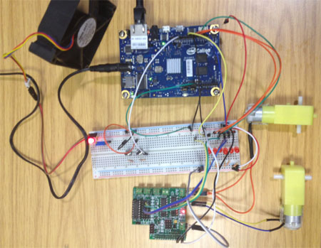
use our Pi-L293D-3 control 2 Motor, also 2 switch input
test,
GPIO input
GPIO output
Analog input
PWM Motor Speed control
We provide a simple GPIO control library, to make
easy control GPIO pin.
Version
GPIO_intel_v10 --
V1.0 28,Feb 2014
GPIO_intel_v101 --
V1.01 05,Mar 2014
Download GPIO_intel Software
tar
format
v1.01
or use the following command from your Galileo
wget http://pridopia.co.uk/ga-pgm/GPIO_Intel_v101.tar
or wget http://pridopia.com/ga-pgm/GPIO_Intel_v101.tar
tar xf
GPIO_Intel_v101.tar
cd GPIO_Intel_v101
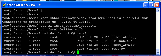
have 1 library file
GPIO_Intel.py
three python example files
Test.py , Robot_Arm.py, Step.py
one License document
LICENSE.txt
If you have any suggestions or
requirement please send an email to

detail as below
python test program
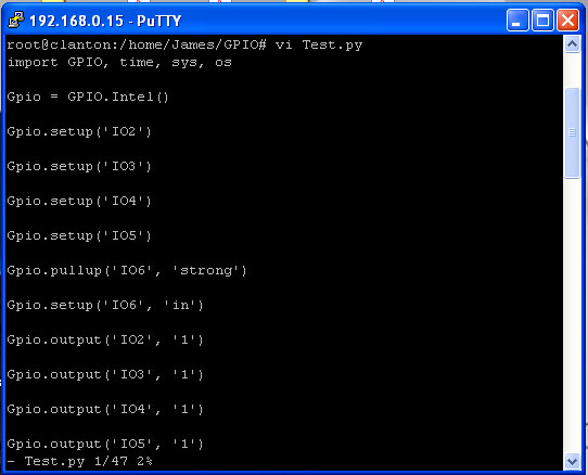
To import the module you need to type
>> import Intel_Gpio
to start / initialize the script you need to run the __init__ function
and assign it to a Variable / Object.
>> GPIO = Intel_Gpio.Intel()
Now you can start to Output, Input, Setup, PWM Pins. The naming layout is
as follows;
For IO Pins from 2 through to 13 the names start with IO and are followed
with the Pin number on
the board. e.g. IO2
For Analogue pins, It is the same as IO Pins but starts with A e.g. A2
For PWM Pins, the command starts with PWM and followed with the number on
the board e.g.
PWM3, PWM5, PWM6.
To output to a Pin you need to set up the Pin.
>> GPIO.setup('IO2') ( This will set IO2
to output by Default )
The next thing you need to do is output a number ( 1 / 0 )
>> GPIO.output('IO2', 1) ( This will output 1 to
IO2 Pin )
To set a Pin as an Input you will need to setup the pin as input by doing
>> GPIO.setup('IO2', 'in') ( setup can either be
'in' or 'out' )
Then you can call input() to get the pin value.
>> print GPIO.input('IO2')
This will print out the current value of IO2,
To set a PWM channel you need to type the following;
>> GPIO.pwm('PWM3', duty='0.1')
( The
Duty is how long the signal is up for. The default
period
length of the signal is 2ms which is 0.2,
So a duty_cycle of 0.1 would be half on, half off )
You can change the Period, The number 0.2 is default and is 2 million
nanoseconds or 2
milliseconds
>> GPIO.pwm('PWM3', period='2000000', duty='1000000')
That is the default command if you just type in GPIO.pwm('PWM3')
To stop a PWM signal or to use normal GPIO again on that pin, type the
command;
>> GPIO.pwm_shutdown('PWM3')
That will disable the PWM and you can return to normal IO Control.
(1) Example 1
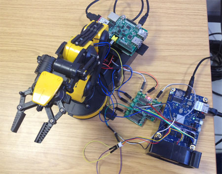
Galileo control 5 motor Robot Arm
Use 1.Rs-pi–L293D-3 6 Motor Board -
Control Robot Arm 5 Motor (M1,M2,M3,M4,M5)
KEYBOARD A,B M5 C,D M4 E,F M3
G,H M2 I,J M1

(2) Example 2
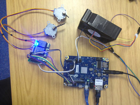
use our Rs- Pi
2803 2 Relay - Step Motor Board & 2 28byj48
5V step Motor