|
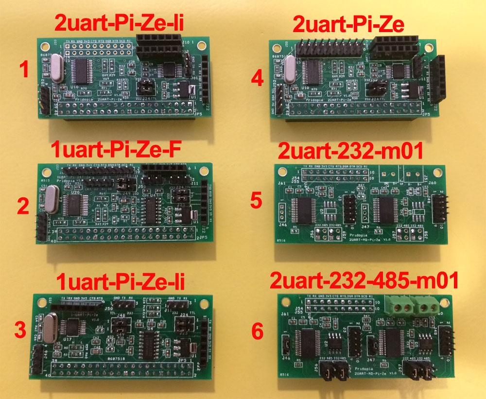
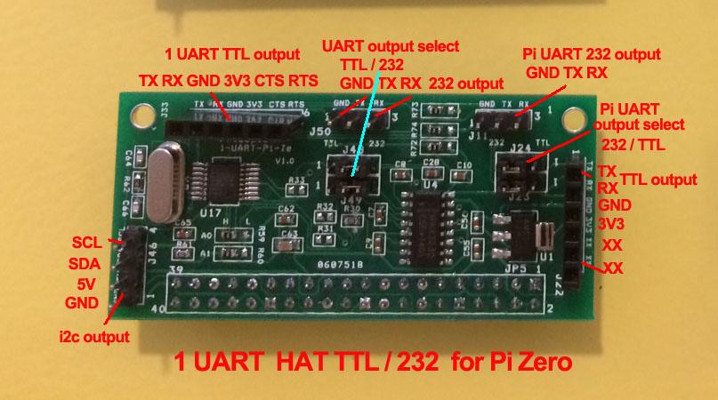
- 1uart-Pi-Ze-li
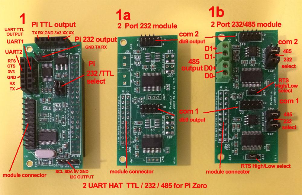
- 2uart-Pi-Ze-li
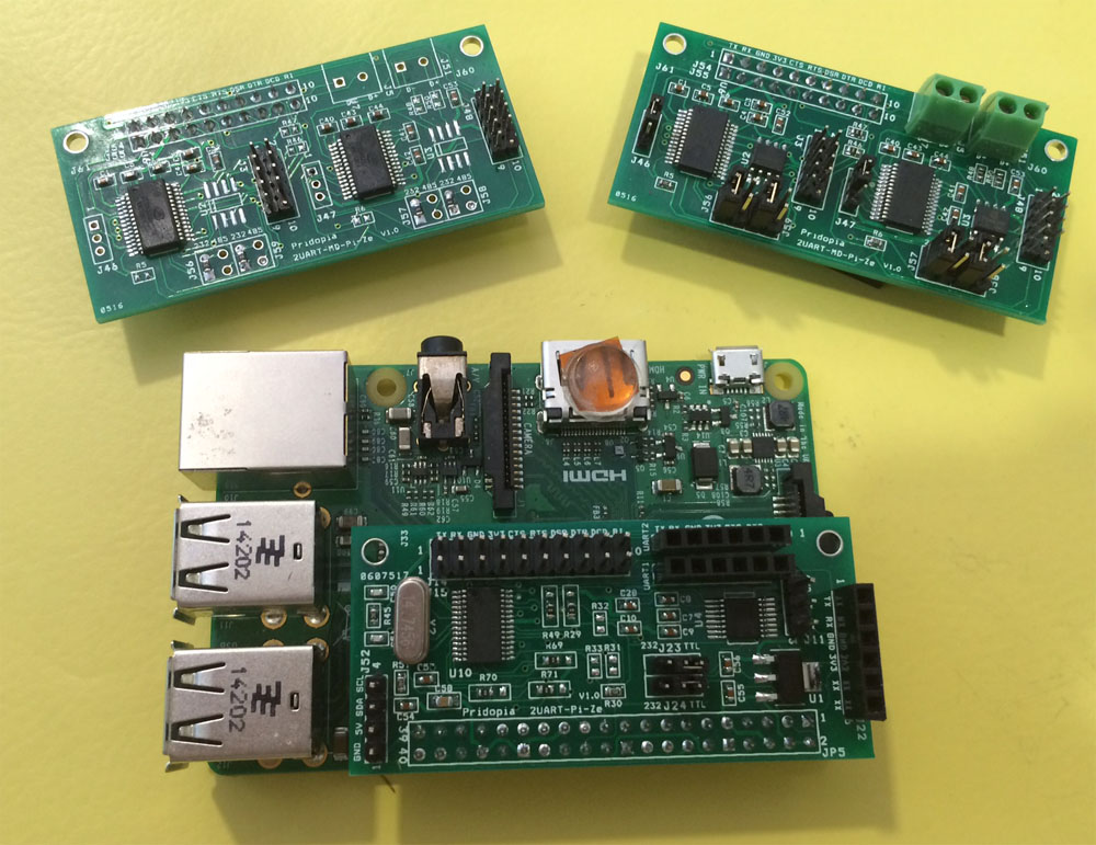
- 2uart-Pi-Ze
3a. 2uart-232-m01
3b. 2uart-232-485-m01
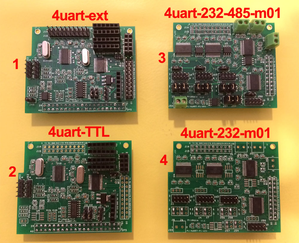
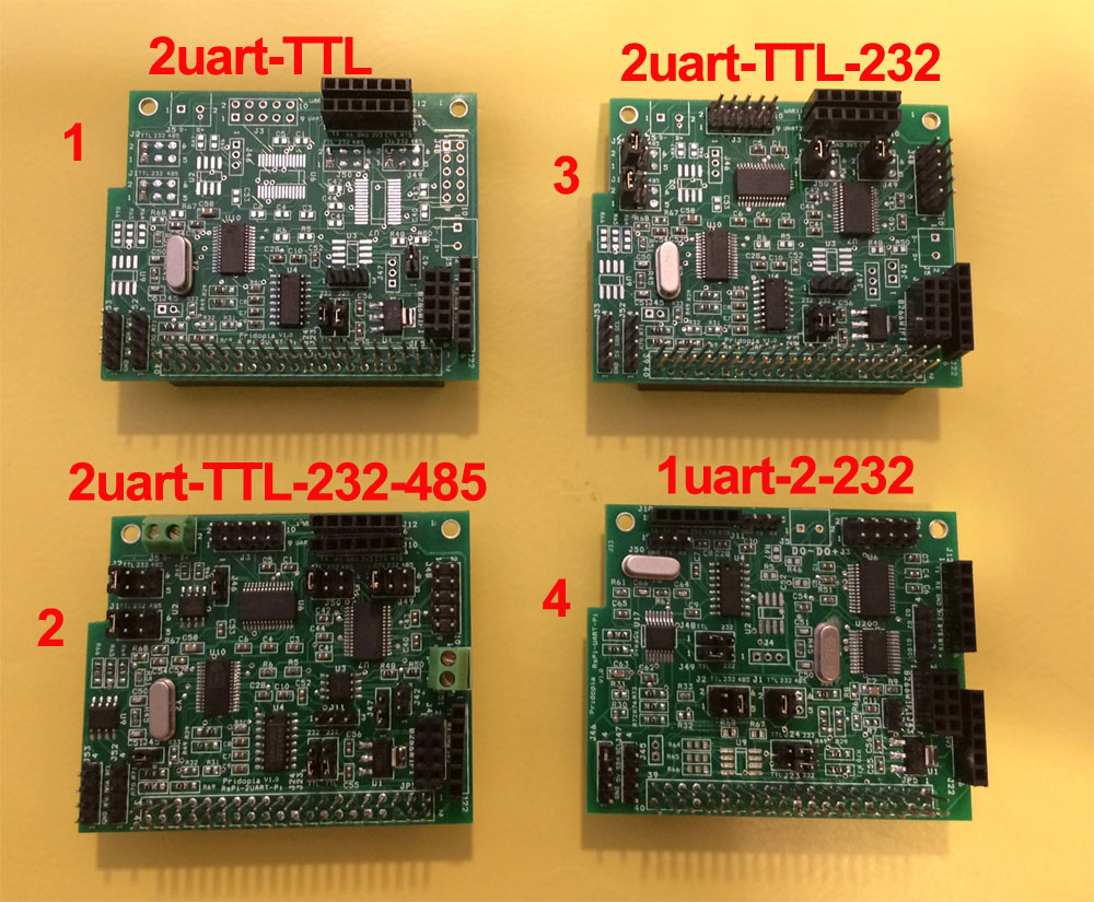
- 4uart-TTL
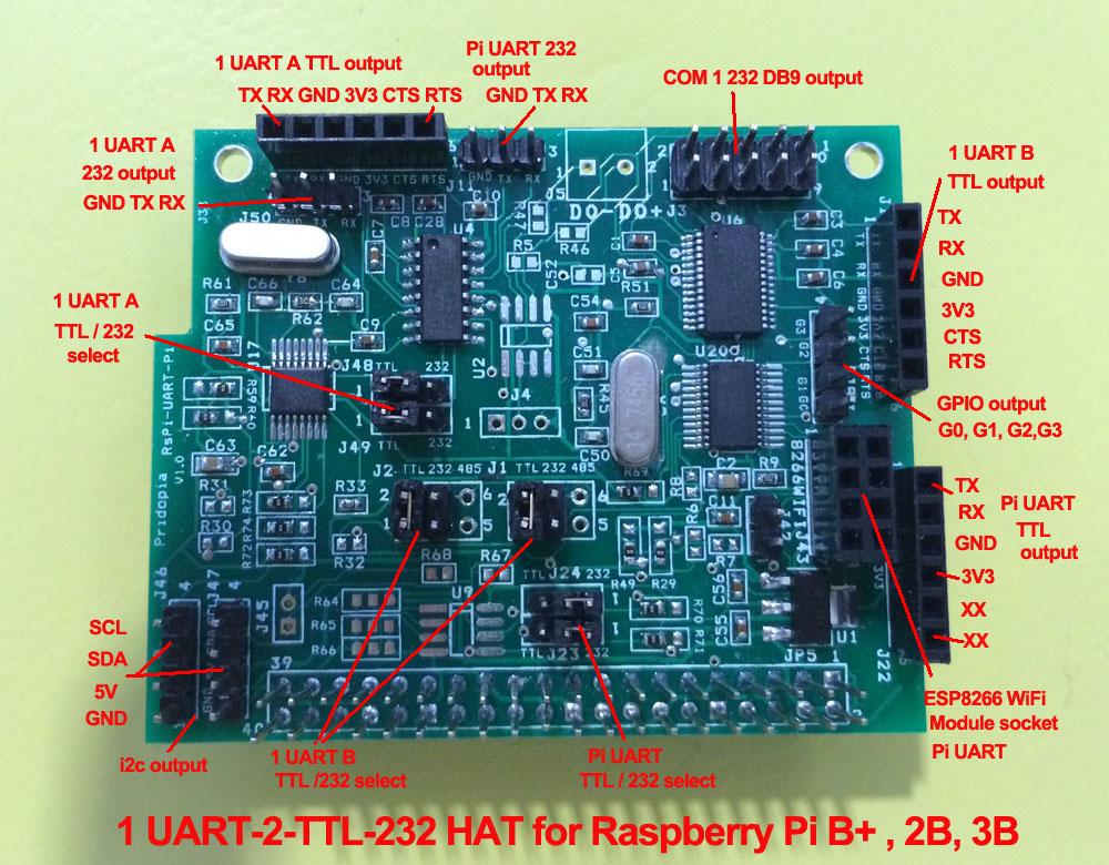
- 1uart-2-232
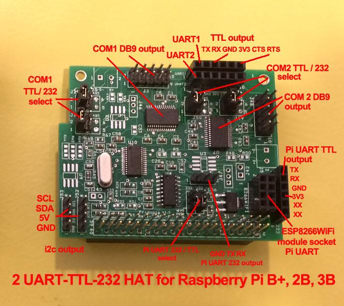
- 2uart-TTL-232
- 2uart-TTL-232-485
- 4uart-ext 8a.
4uart-232-m01
8b.4uart-232-485-m01
Project Background
During development
/ research for a project which needs more than 1
UART Port, the common replacement for the Raspberry
Pi is the "Arduino MEGA". This is because the MEGA
provides 4 UART's which can be used at the same time
creating a multi UART device.
When using UART on the Raspberry Pi you are very
limited on how you work around this limitation, but
we also know that the Pi 3B has a built in WiFi &
Bluetooth module. In the Raspberry Pi 3B the
Bluetooth uses the only UART which further limits
the use of the Pi.
Most solutions for
External UART controllers come as a USB to UART
converter, which takes up space and brings the
design out of the Raspberry Pi's small form factor.
To counteract all the limitations of the Raspberry
Pi, we have built a board which simply connects
through the Pins on the Raspberry Pi as usual, but
include access to extra UART's without limiting the
Pi any further or without a special image. Included
is our own software which manages, controls, and
watches the UART ports.
The software comes as a terminal program, and
multiple GUI programs, each will report the port
location for easy to use manageable hardware
integration.
WHAT IS IT?
UART HAT is Add-on board for Raspberry Pi which provides one/ two/Four additional RS232 & TTL serial ports with flow control
which are 3.3 V compatible in addition to the original Serial Port of Raspberry PI.
WHAT IS THE USE OF UART HAT?
As we know the Raspberry Pi only has one Serial Port with only one RX and TX, which is primarily used for Debugging and SSH.
If we need to connect any serial devices to Raspberry Pi we have to disable debugging and then we need to connect our device.
So if you need to connect up a UART device such as a GPS or GSM Modem, you cannot SSH or debug the Raspberry Pi with a serial connection.
To overcome the all these problems we have came up with UART HAT which helps to Connects Multiple Serial Devices Like GPS, GSM Modem,
Bluetooth 2.0/4.0 module , Arduino Pro Mini,
Arduino serials and whole array of devices to Raspberry Pi main board without using the main RX, TX pins on the main board.
Serial Port device list
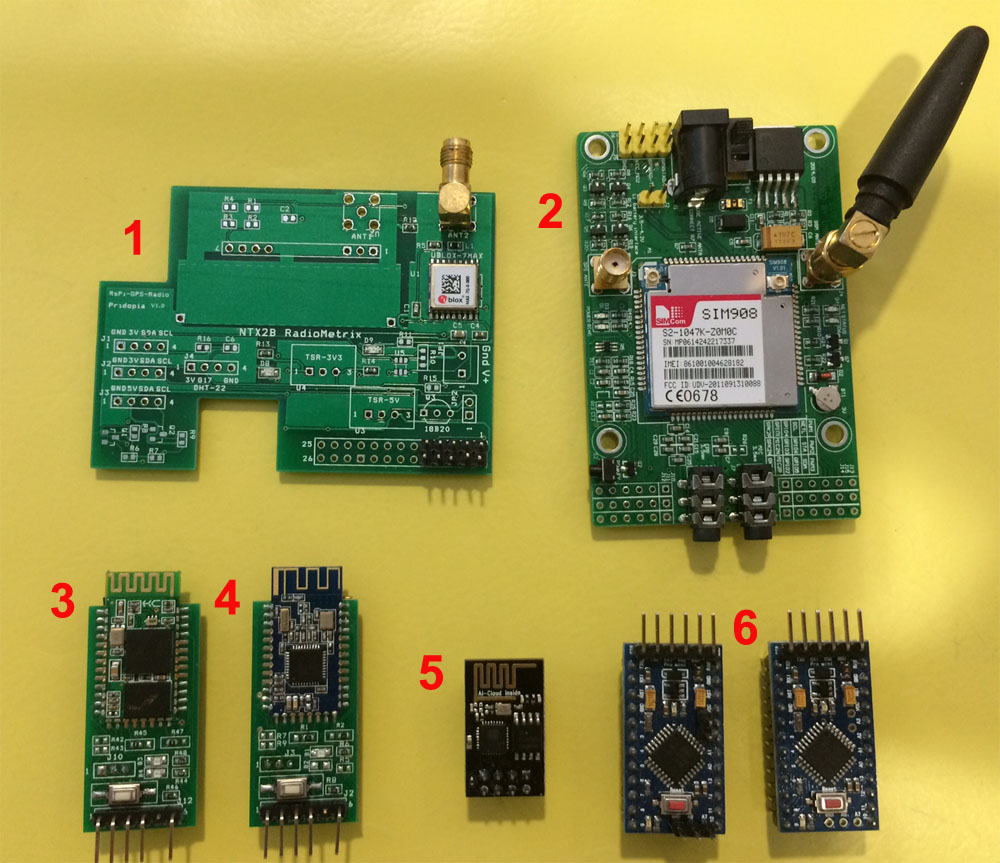
- P-HAB GPS-Lite Module
- SIM908-C EVB GPRS/GPS Module
- Bluetooth 2.0
- Bluetooth 4.0 BLE
- ESP8266 WiFi Module
- Arduino Pro Mini x2
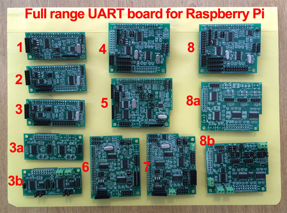
I2C to UART HAT board from 1 UART to 2 UART up to 8 UART
- 2 UART TTL + one UART(Pi)
- 1 UART TTL + one UART(Pi) with
extra 4 GPIO output
- 1 UART TTL + one UART(Pi)
- 2 UART TTL + one UART(Pi) with
Extension socket
- 2x RS232 extension Module
- 2x RS232 /2x RS485 extension
Module
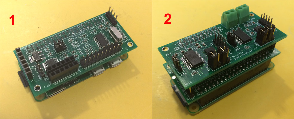
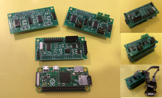
1. 2uart-Pi-Ze plug in Pi Zero
2. 2uart-Pi-Ze+2uart-232-485-m01 Module plug
in Pi Zero
2uart-Pi-Ze-Li demo
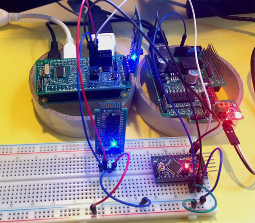
3UART demo ( 2 - 2uart-Pi-Ze-Li,
1 - Pi)
1. Arduino Mini Pro
2 Bluetooth 2.0
3. Bluetooth 4.0 BLE (Pi)
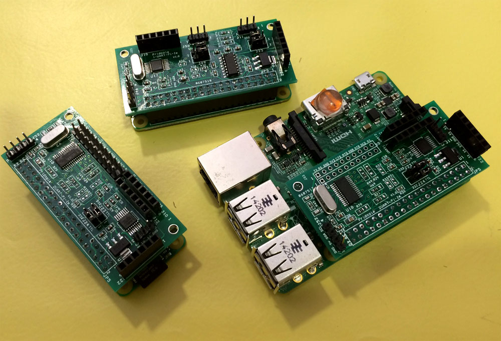
UART Pi Zero HAT plug in B+/ 2B / 3B
4UART products can use up to 8 UART in one
Pi
- 4 UART Pi (4 UART TTL output
/HAT EEPROM) with Extension socket
- 4 UART Pi (4 UART TTL output)
- 4 x RS232 /4x RS485
Extension module
- 4x RS232 Extension module
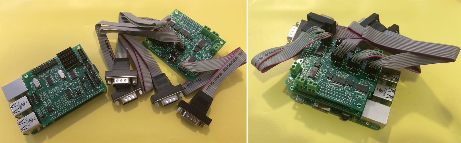
4uart-ext board with
4uart-232-485-m01
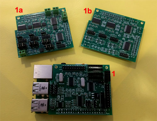
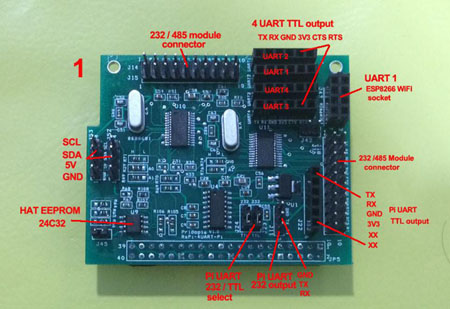
1. 4 UART Pi (4 UART TTL output
/HAT EEPROM) with Extension socket
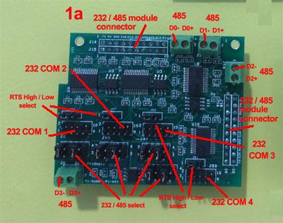
1a. 4 x RS232 /4x RS485
Extension module
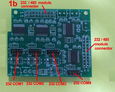
1b. 4x. RS232 Extension module
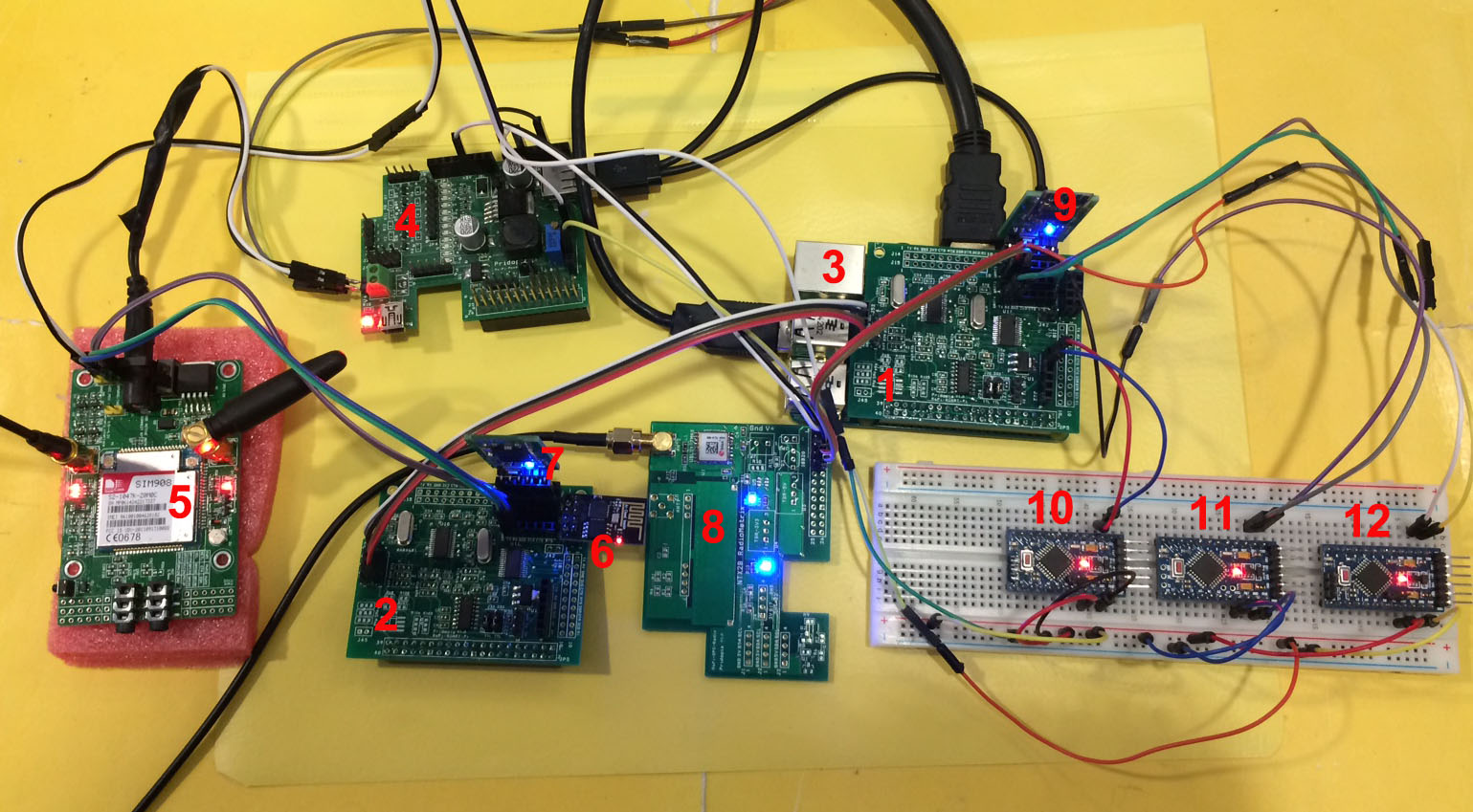
4 UART HAT demo
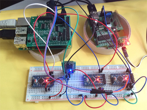
uart1, uart3, uart4 arduino mini Pro x3
Bps: 9600
uart2 bluetooth 2.0 x1 Bps:
38400
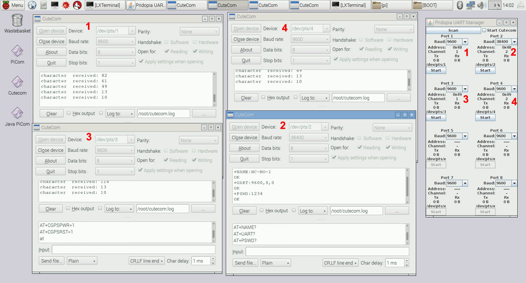
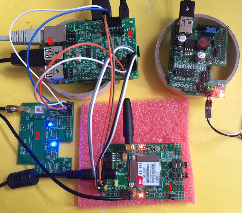
9UART demo 8 UART ( 2x 4 UART HAT )+ 1 UART
Pi

- Pi-UART-4-TTL ( 4 UART HAT )
- Pi-UART-4-TTL ( 4 UART HAT )
- Raspberry Pi 2B
- Pi-PSU ( Pridopia Pi Power Supply )
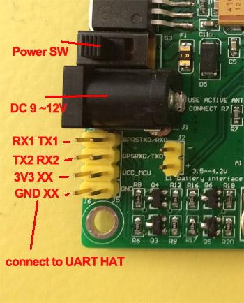
- SIM908-C EVB 1.0 GPRS+GPS Module ( 2 UART )
- ESP8266WiFi module ( 1 UART )
- Bluetooth 2.0 ( 1 UART )
- Pi-HAT-Lite GPS Module ( 1 UART )
- Bluetooth 4.0 BLE ( 1 UART )
- arduino mini Pro ( 1 UART Pi )
- arduino mini Pro ( 1 UART )
- arduino mini Pro ( 1 UART )
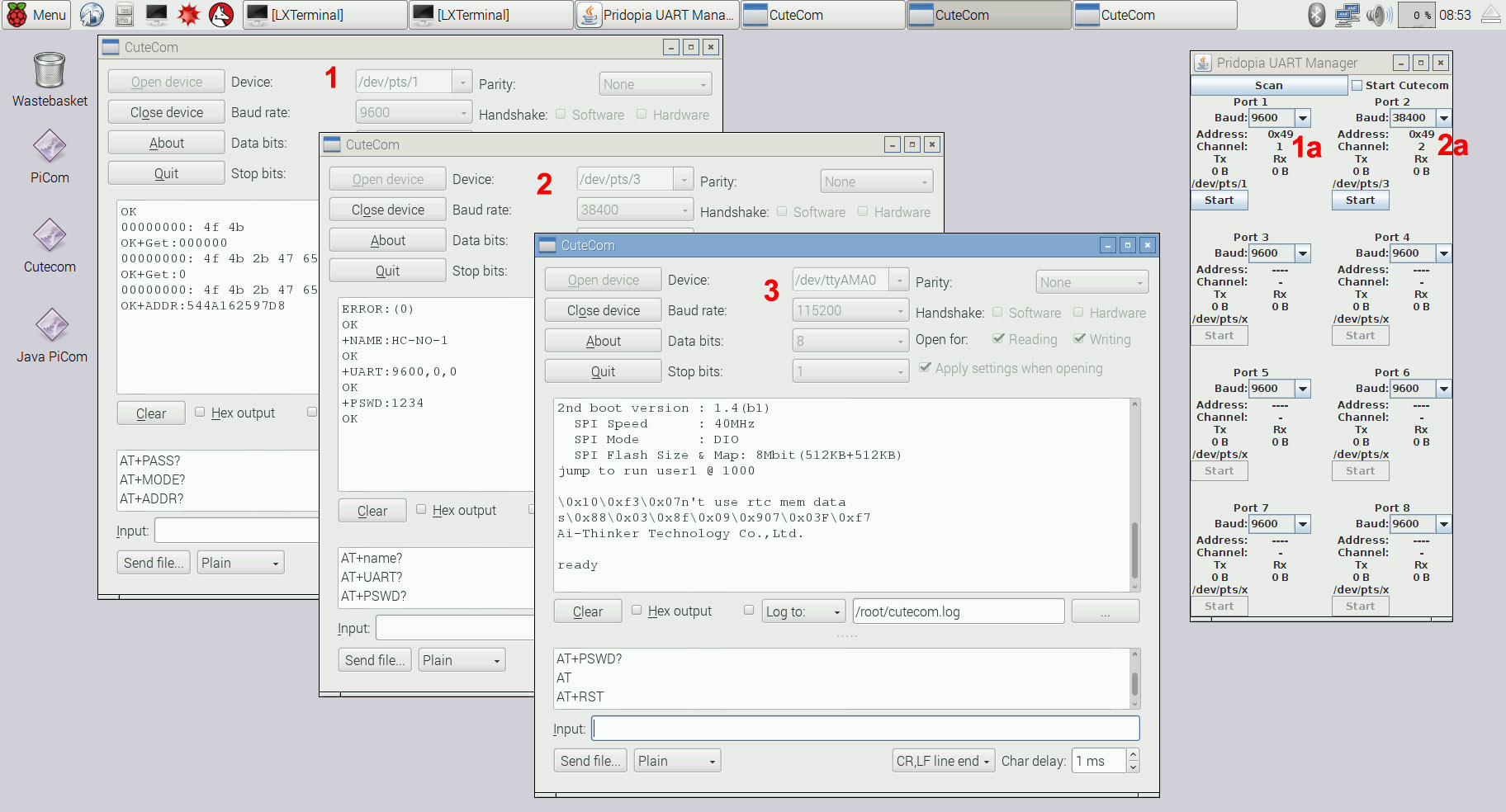
1. SIM908-C EVB 1.0 GPRS (Port 8 bps 115200 )
2. SIM908-C EVB 1.0 GPS ( Port 7 bps 115200 )
3. Bluetooth 2.0 ( Port 6 bps 38400 UART )
4. ESP8266WiFi module ( Port 5 bps 115200 )
I2C to UART HAT board from 1 UART to 2 UART up to 8 UART
- 2 UART TTL + 1 Pi UART
- 2 UART TTL + Pi UART + RS232/RS485
(Full 2 Port DB9 RS232 Output)
- 2 UART TTL + Pi UART + RS232 (Full 2
Port DB9 RS232 Output)
- 2 UART TTL ( 1X Full DB9 RS232 &
1X TTL & 232 Output )
& 4 extra GPIO + Pi UART
RS232 DB9 output example
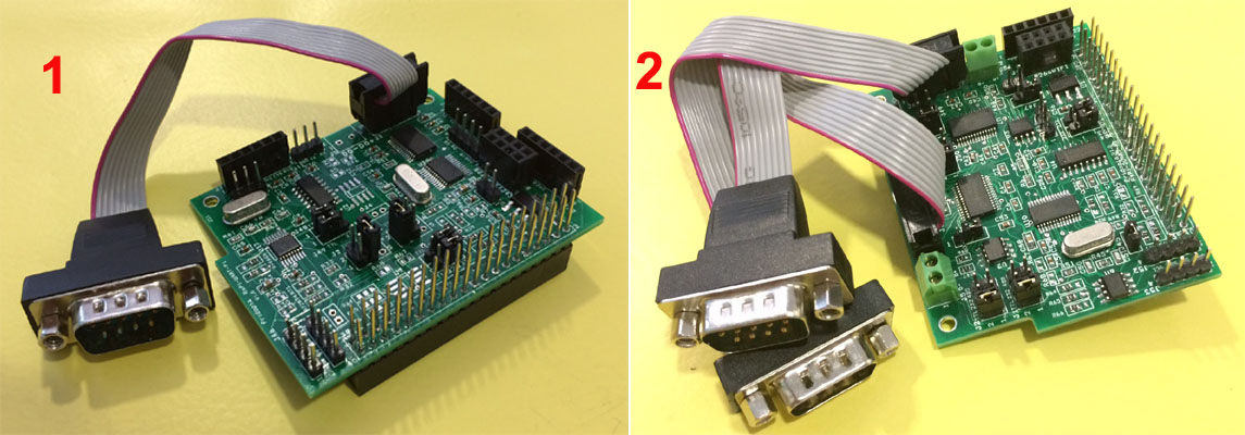
- 1 UART TTL ( Full DB( RS232 & TTL Output )
+ 1 UART TTL + Pi UART
- 2 UART With RS232/422 (Full DB9 RS232
Output) + 1 Pi UART
Example 1
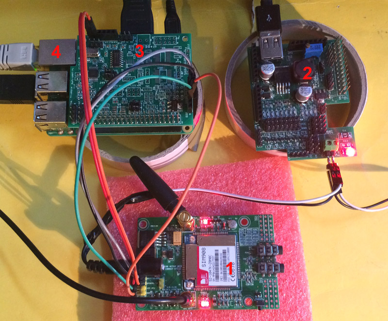
- SIM908-C EVB 1.0 GPRS+GPS Module ( 2 UART )
- Pi-HAT-Lite GPS Module ( 1 UART )
- Pi-PSU ( Pridopia Pi Power Supply )
- Pi-UART-2-TTL ( 2 UART HAT )
- Raspberry Pi 2B
Needs 3 UART Signals to control 1 GPS board & GPRS, and GPS board.
Example 2
- SIM908-C EVB 1.0 GPRS+GPS Module ( 2 UART )
- Pi-PSU ( Pridopia Pi Power Supply )
- Pi-UART-1-TTL ( 1 UART HAT )
- Raspberry Pi 2B
GPRS connect to Pi UART & GPS
connect to 1 UART HAT
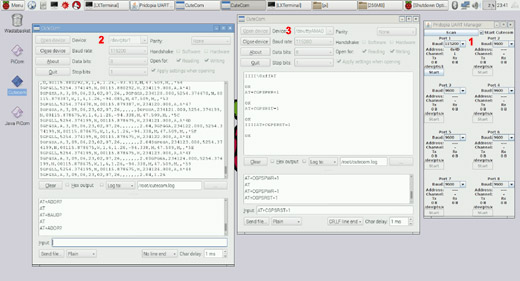
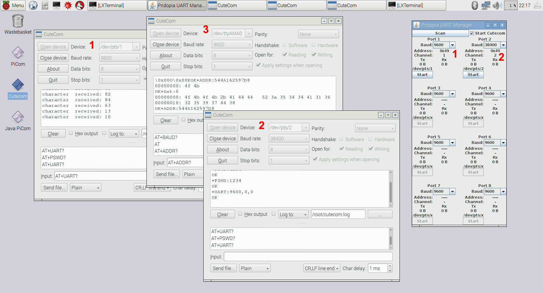
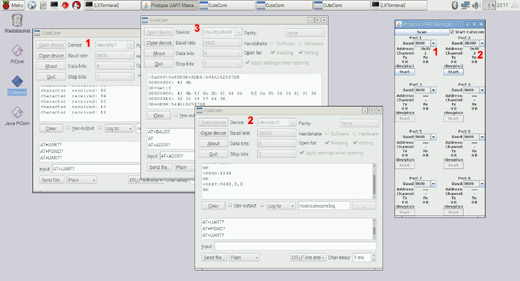
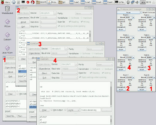
- GUI Interface for Serial Port Monitoring & Control
- Cutecom Status for 1 UART HAT ( GPRS
115200 Baud )
- Cutecom Status for Pi UART ( GPS 115200 Baud )
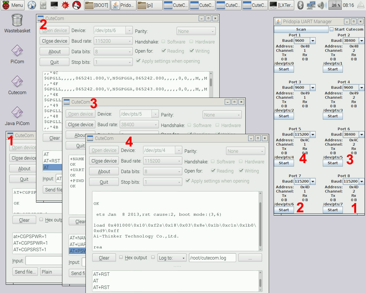
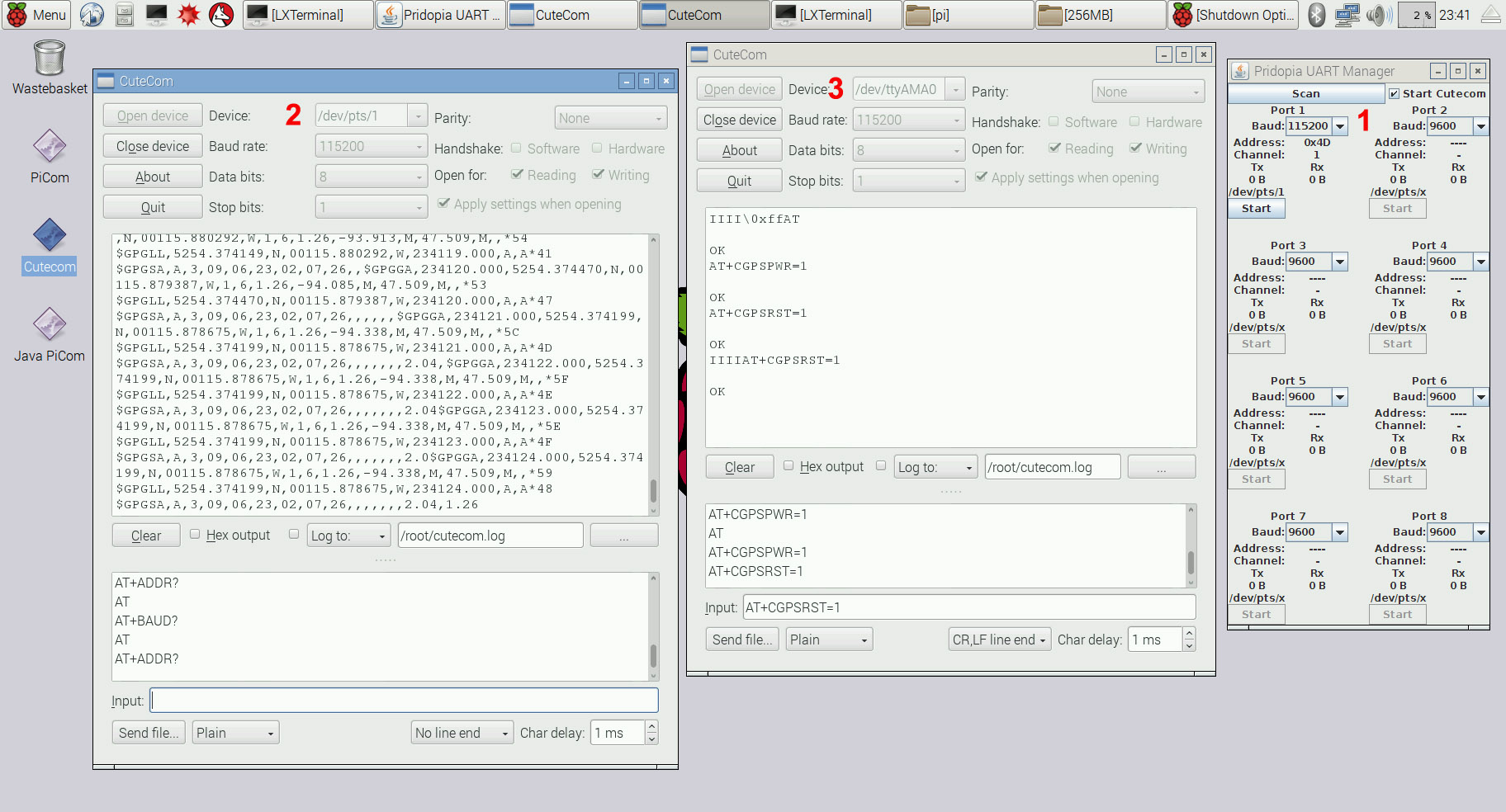
Example 3
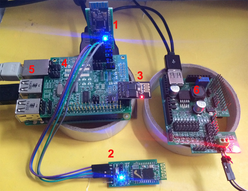
- Bluetooth 4.0 BLE ( 1 UART )
- Bluetooth 2.0 BLE ( 1 UART )
- ESP8266 WiFi Module ( 1 UART, Using Pi RX/TX Signal )
- Pi-UART-2-TTL ( Provides 2 UART )
- Raspberry Pi 2B
- Raspberry Pi-PSU ( Power Supply to boards )
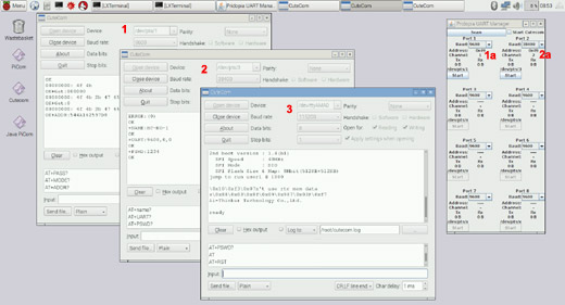
1a,2a GUI Interface for Serial Port Monitoring & Control
1. Cutecom Status for UART HAT Port 1 ( Bluetooth 4.0 BLE 9600 Baud )
2. Cutecom Status for UART HAT Port 2 ( Bluetooth 2.0 BLE 9600 Baud )
3. Cutecom Status for Pi UART ( ESP8266 WiFi Module 115200 Baud )
Use Raspbian Jessie Image
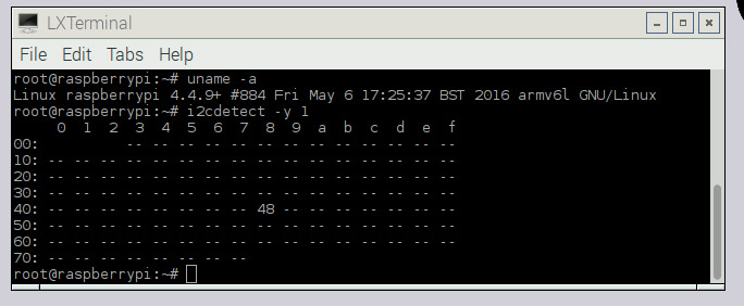
Version: May 2016 - Release Date 2016-05-10 Kernel Version : 4.4
-
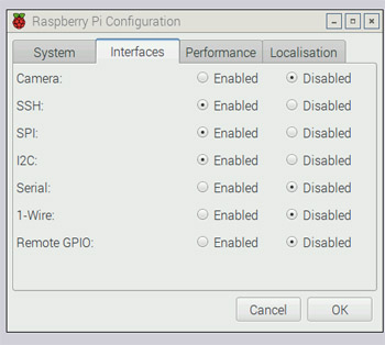
Enable I2C & SPI, Disable Serial Console Port
-
Install Python SMBus and Cutecom;
											sudo apt-get install python-smbus
											sudo apt-get install cutecom
-
i2cdetect -y 1 ( and detect what address your chip is on )
-
Automatic Login for LightDM
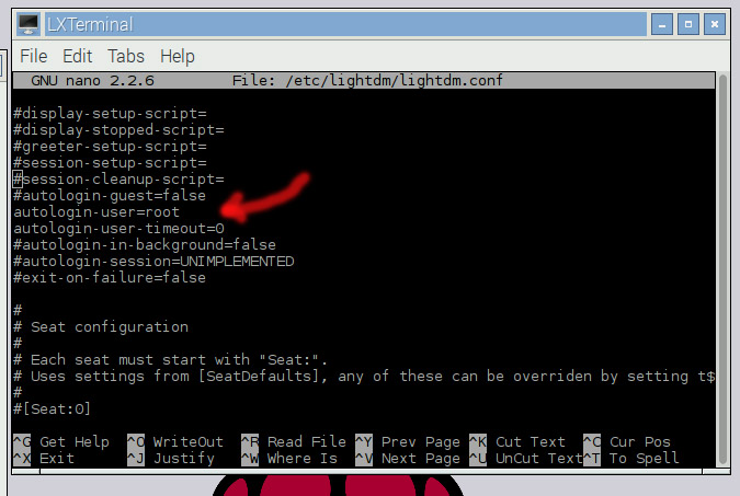
Open a file browser or terminal and direct yourself towards /etc/lightdm/
Now backup the lightdm.conf to your desktop just incase things don't workout.
-
Uncomment the lines;
autologin-user=USERNAME
autologin-user-timeout=0
Replace the USERNAME with your username ( pi or root )
Ctrl + X then Y to save in the nano editor
-
Run the command so that the changes take effect;
dpkg-reconfigure lightdm
-
Serial Interface / Control Panel
- GUI Serial Port Interface / Control Panel
- GPRS Cutecom Terminal ( SIM908 GPRS 115200 Baud, Pi UART )
- GPS Cutecom Terminal ( SIM908 GPS 115200 Baud, I2C UART
Port 2 )
- GPS Cutecom Terminal ( HAB-Lite GPS Module 9600 Baud, I2C UART Port 1 )
- Cutecom Shortcut
- Java PiCom Serial Port GUI Shortcut
- I2CDetect detecting 0x48 I2C UART Board
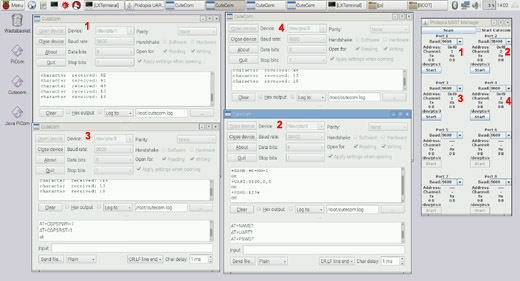
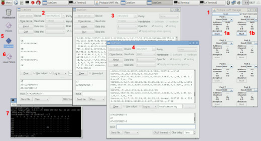
Serial GUI Control Panel
Control up to 8 Serial Ports
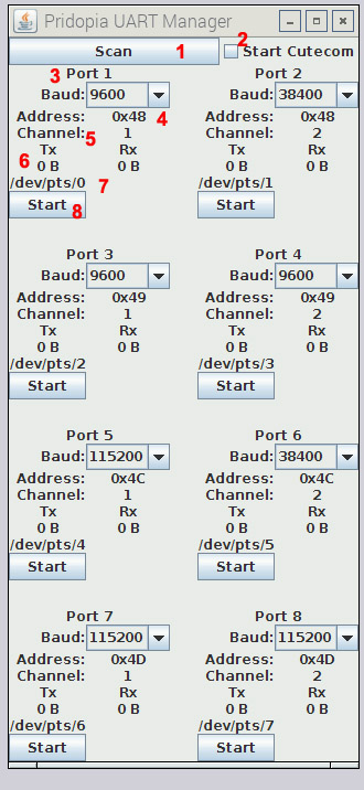
-
1. Scan: Scan for available UART
devices.
-
2. Launch cutecom together when starting Serial Port.
-
3. Port number in system
-
4. Baud Rate choose
-
5.6.7. UART Port Information:
Port Address 0x48,0x49, 0x4c, 0x4d
Chip Address Location, Channel Number ( 1 / 2 ), TX and RX receive counter,
and Serial port Location /dev/pts/X
-
8. Start : Start UART port
Also provided is a terminal command mode to activate serial ports through a terminal / ssh.
You can also activate a serial port on boot up with the provided software.
Commands for starting the serial ports via command line;
									./Pi8s -a ADDR -c CHANNEL -b BAUD -s DEVPTS

									ADDR = Address of Serial Port e.g. 0x48, 0x49, 0x4C, and 0x4D

									CHANNEL = Channel of serial Port ( 1 / 2 )

									BAUD = Baud Rate for the Serial Port

									DEVPTS = PICOM Service Number ( Will direct the filename to /dev/picomX where X = your number )
For example, To start a serial port from 0x49, on channel 2 with 115200 Baud run the following;
									./Pi8s -a 0x49 -c 2 -b 115200 -s 1

									This will activate the serial port and then set /dev/picom1 to your serial port location /dev/pts/X
|